Guides / Process
Surface Integrity in Inconel Machining: White Layer and Residual Stress Explained
October 23, 2026
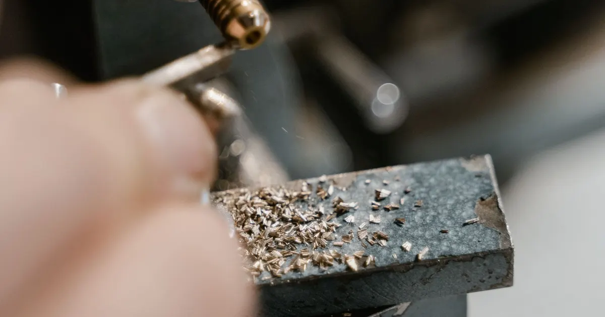
A finished Inconel part can pass every dimensional check and still carry damage that a caliper will never find. The surface a cutting tool leaves behind is not just a shape. It is a thin layer of metal that has been heated, squeezed and sometimes smeared, and its condition decides how the part behaves in fatigue. Buyers of rotating hardware and cyclically loaded parts hear the term surface integrity for this reason. It describes the metallurgical and mechanical state of the surface after machining, not just how smooth it looks.
What surface integrity means
Surface integrity covers several things at once. There is the geometry of the surface, including roughness and waviness. There is the metallurgy, meaning the grain structure, the hardness and any altered layer within a few tens of micrometers of the surface. And there is the stress state, meaning whether the surface is in compression (good for fatigue) or in tension (bad). A part has good surface integrity when the machining left a surface that is smooth, metallurgically the same as the bulk and in compression or close to neutral.
Inconel is more sensitive to this than most metals. It holds heat at the cut, it work-hardens and it keeps its strength at temperature, so the tool pushes harder and heats the surface more than it would on steel. That makes it easy for a worn tool or a rushed finishing pass to leave damage that looks like a good surface.
White layer, smearing and other defects
Several defect types appear in machined nickel alloys:
- White layer. A thin, hard, featureless layer that shows up white under the microscope after etching. In conventional machining it comes from severe heat and deformation at the edge. In electrical discharge machining it is a recast layer formed from re-solidified metal.
- Smeared metal. When a tool rubs instead of cutting, the surface metal is dragged across itself and can fold over small gaps. This can hide cracks from inspection.
- Grain distortion. The grains near the surface are stretched in the cutting direction. A thin distorted layer is normal. A deep one means heavy cutting.
- Micro-cracks. In severe cases the damaged layer cracks under residual stress, usually in grinding or EDM.
- Tearing and built-up edge marks. Metal welds to the tool, then tears away, leaving pits and ridges.
Our note on why Inconel work hardens explains the root cause, and our page on grinding Inconel parts covers a process where thermal damage is a particular risk.
Residual stress
Every cutting process leaves residual stress in the surface. Sharp tools, moderate speeds and light cuts tend to leave compressive stress, which resists crack growth and extends fatigue life. Worn tools, high speeds and heat tend to leave tensile stress, which does the opposite. The depth of the stressed layer is usually under 100 micrometers in finishing, but it is the part of the metal where fatigue cracks start.
Residual stress also moves parts. When a heavily stressed part is cut free from a plate or machined on one side, the stress rebalances and the part bows. Shops manage this by roughing, relieving stress and then finishing with light cuts. Our note on heat treatment sequencing for 718 shows how that sequence fits with aging.
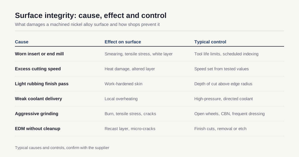
| Cause | Effect on the surface | Typical control |
|---|---|---|
| Worn insert or end mill | Smearing, tensile stress, white layer | Tool life limits, scheduled indexing |
| Excess cutting speed | Heat damage, altered layer | Speed set from tested values |
| Light, rubbing finish pass | Work-hardened skin | Minimum depth of cut above edge radius |
| Weak coolant delivery | Local overheating | High-pressure, directed coolant |
| Aggressive grinding | Burn, tensile stress, cracks | Open wheels, CBN, frequent dressing |
| EDM without cleanup | Recast layer, micro-cracks | Finish cuts, removal or etch |
How shops control it
Control starts with a defined process. A shop that runs surface-critical parts fixes the tool type, the speeds and feeds, the tool life limit and the finishing sequence, then proves the process on a sample before cutting the real part. Typical practices include:
- Using fresh, sharp inserts or end mills for the final pass on each critical surface.
- Keeping finishing cuts above a minimum depth so the tool cuts instead of rubbing.
- Using high-pressure, well-aimed coolant to keep the cutting zone cooler.
- Taking a light final pass, sometimes a spark-out pass, to remove any damaged layer from earlier cuts.
- Verifying the process by examining sample coupons or sacrificial parts.
Some customers require approved machining parameters, where the shop uses only the speeds, feeds and tools qualified for that part. If your part falls under such a requirement, say so at the start. A shop cannot be added to an approved process after the order is placed.
Measuring and verifying
Four methods are common. A metallographic section cuts a sample, polishes and etches it and examines the surface under a microscope for white layer, smearing and distortion depth. Microhardness testing measures hardness at set depths below the surface, showing whether the surface is harder than the bulk. X-ray diffraction measures residual stress in a thin layer without cutting the part. And fluorescent penetrant inspection finds surface-breaking cracks, as described in our note on fluorescent penetrant inspection for Inconel parts.
Most shops verify the process on coupons made alongside the parts, not on every production piece. The report from that coupon test is part of the documentation package for critical parts.
Fixing damage after machining
Where the machined surface cannot be trusted, post-machining treatments can restore a good state. Shot peening bombards the surface with small media to create compressive stress, and it is common on fatigue-critical features such as fillets and bolt holes. Vibratory or abrasive finishing can remove a thin layer, including smearing and fine burrs. Chemical or electrochemical removal takes off a controlled depth, which is sometimes used to remove white layer from EDM surfaces. Each treatment adds cost and has its own process specification, so name it on the drawing if needed.
Order matters. Penetrant inspection should come before peening, because peening can close surface cracks and hide them. Check with the shop and the design authority about the right sequence.
Why a smooth surface is not proof
Roughness is the easiest surface property to measure, so it is the one most drawings call out. It is also a poor guide to surface integrity. A worn insert can leave a bright finish at Ra 0.8 micrometers on a layer that is smeared and in tension. A fresh insert can leave a slightly rougher surface that is in compression and metallurgically clean. Buyers who write only a roughness value are effectively asking for a look, not for fatigue performance.
Process control is the answer. A shop with fixed tooling, tested parameters and a record of tool changes will give you a more reliable surface than a shop that inspects roughness at the end. When you compare quotes, ask how the shop decides when to change a finishing tool and how it proves that a surface-critical feature was cut with a tool inside its limit. A concrete answer, such as a counted number of parts per edge, is worth more than a general assurance.
Cost of controlling it
Control adds cost in three places: more tool changes, since edges are replaced before they are worn out; more inspection, since sections and hardness traverses take time in the lab; and lower cutting speeds on the finishing pass. A part with one surface-critical feature may add a small percentage to the price. A part with many such features, plus a verification report and peening, can add much more. That is a reasonable cost where fatigue life is the concern, and a waste where it is not, which is why marking only the critical surfaces matters.
When to specify it
Surface integrity requirements add cost, so use them where they matter. Candidates include rotating components, parts in hot or cyclically loaded sections, fasteners and critical holes. Static housings, brackets and fixtures do not usually need them. Our guide to Inconel in aerospace describes the kinds of parts where fatigue life is the concern.
What to include on the RFQ
State the requirement in terms the shop can price. Include these items:
- Which surfaces are critical, marked on the drawing.
- The governing specification, if there is one, or the maximum allowed white layer and altered layer depth.
- Whether approved machining parameters apply.
- The verification method required, such as sectioning, hardness traverse or residual stress measurement.
- Any post-machining treatment such as shot peening.
Closing checklist
Before you send the drawing, decide whether the part needs surface integrity control, mark the critical surfaces and name the specification and verification method. Without that, shops will quote normal finishing and the surface may not meet your need. When the drawing is ready, send an RFQ and we match you with up to three shops that already machine nickel alloys for fatigue-critical work.
Frequently asked questions
What is white layer?
White layer is a thin, featureless layer on the surface of a machined part that appears white or pale after a metallographic section is polished and etched. It forms when heat and plastic deformation at the cutting edge change the structure of the metal. It is usually very hard and brittle, so specifications for critical parts limit or forbid it.
Does every Inconel part need surface integrity control?
No. Static brackets, housings and fittings rarely do. Rotating parts, parts under cyclic load and parts in hot sections often do, because surface damage can start fatigue cracks. If you are not sure, ask the designer or add the question to your RFQ so each shop answers it.
How is residual stress measured on a machined part?
The most common method is X-ray diffraction, which measures stress in a very thin surface layer without cutting the part. Another method removes layers of metal one at a time and measures how the part changes shape. Shops usually test sample parts or coupons made with the same process instead of testing every production part.
Need a quote for this part?
Send the drawing. We match you with up to 3 Inconel-capable shops and reply within 24 business hours.
Get matched with an Inconel shop