Guides / Process
Machining 3D Printed Inconel 718: Supports, HIP and Finish Stock
October 26, 2026
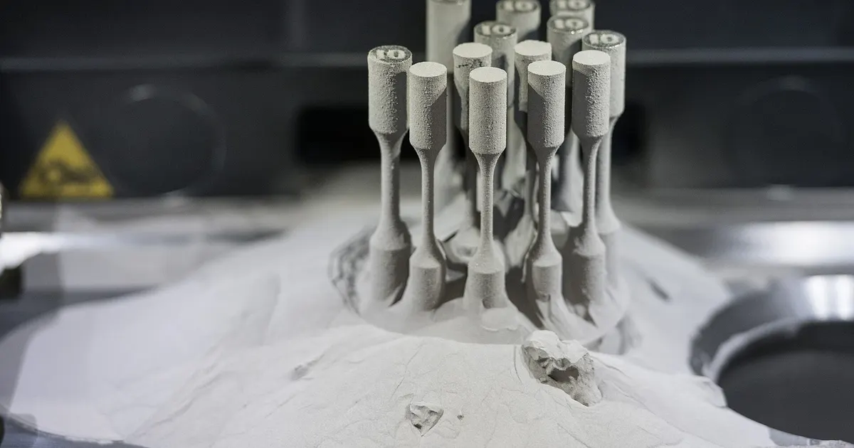
Additive manufacturing gets an Inconel part close to its final shape without carving it from a block, but almost no printed part is finished on the printer. Surfaces that seal, bear load or mate with another part need machining, and threads and holes with tight tolerances do too. Printed Inconel 718 behaves differently from wrought bar, so the plan for machining it starts well before the first cut.
How a printed part differs from bar
Laser powder bed fusion (LPBF) builds a part layer by layer by melting thin layers of metal powder with a laser. Each layer cools very quickly, which locks in residual stress and a fine, directional grain structure. The surface is rough, with partly melted powder particles stuck to it, and the downward-facing surfaces, which need supports, are the roughest.
Three consequences matter to a machinist. The part is stressed and can move when released. The surface is rough and uneven, so the first cuts see variable depth. And the properties depend on build direction, so a part may be stronger in one direction than another until heat treatment evens it out. Our guide to Inconel machining for buyers covers the base material, and this article covers what changes for printed parts.
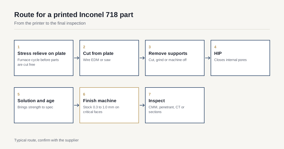
The usual process route
The sequence for a printed 718 part is well established, though details change by specification and customer.
- Stress relief on the build plate. The plate and parts go into a furnace before anything is cut free. This relaxes the residual stress that would otherwise distort the part.
- Remove from the plate. Wire EDM is the common method, because it cuts without force. A band saw is used on some parts.
- Remove supports. Supports are cut, ground or machined off, and the witness marks are blended or machined later.
- Hot isostatic pressing (HIP). The part sits at high temperature under high gas pressure, which closes internal porosity. Many aerospace and energy specifications require it for printed critical parts.
- Solution treatment and aging. The standard 718 heat treatment follows, to reach the strength the specification asks for. Our note on heat treatment sequencing for 718 shows how wrought and printed routes compare.
- Final machining. Critical surfaces, holes, threads and datum features are machined to size.
- Inspection. Dimensional checks, penetrant inspection and, where required, CT scanning or section checks.
Standards such as ASTM F3055 cover printed nickel alloy 718 made by powder bed fusion, and customer specifications add their own requirements. Quote the one that applies.
Supports and witness marks
Supports hold overhanging features during the build and conduct heat away from them. They must be removed, and where they touched the part they leave a rough witness mark. Good designers place supports on surfaces that will be machined anyway, so the mark is cut away. Where supports sit on a surface that cannot be machined, such as an internal channel, removal is harder and the mark may stay, which needs to be accepted on the drawing.
Shops remove supports by cutting, grinding or milling, and then machine the stock off the interface. Plan this early. A drawing that does not say which surfaces are machined and which stay as-built leaves the shop guessing and the buyer exposed to rework.
Finish stock and surface condition
The as-built surface of an LPBF part is rough, commonly in the range of Ra 6 to 15 micrometers on vertical walls and rougher on down-facing surfaces. A surface that must be machined needs enough stock to cut below the rough layer and below any shallow subsurface porosity. Typical practice is 0.3 to 1.0 millimeter of stock on machined surfaces, with more on large parts or parts that distort.
| Stage | What changes | Typical figure |
|---|---|---|
| As-built wall | Rough, partly melted powder | Ra 6 to 15 µm |
| After stress relief and plate removal | Small distortion | Varies with geometry |
| After HIP | Pores closed, small size change | Small, usually a fraction of a percent |
| Stock on machined faces | Leaves room to clean up | 0.3 to 1.0 mm |
| After finish machining | Machined surface | Ra 0.8 to 3.2 µm typical |
These are typical values. The printer operator, the machinist and the designer should agree real numbers on the first part.
How the cutting differs
Once the part is heat treated, cutting is similar to wrought 718 at the same hardness, with a few differences. Surface scale and fused powder particles are abrasive and wear the tool at the start of a cut, so roughing passes use tougher tooling and take enough depth to get below the rough layer. Internal porosity left after incomplete HIP can show up as small pits on the machined surface, so a shop watching for pits can alert you before more work is invested. And because the first cut is uneven, fixtures that locate on printed surfaces can shift, so many designs include machined datum features that the shop cuts first and then uses to locate every later operation.
The base machining advice still applies. Our guide on why Inconel work hardens explains why tools must stay sharp and cutting steady.
Problems that show up on first parts
First builds of a new geometry usually teach something. The most common surprise is distortion: thin sections, long flat faces and unsymmetric designs move when they come off the plate, and the part ends up outside the stock allowance that looked generous on paper. Another is trapped powder, since internal channels can hold loose powder that must be cleared before heat treatment, where it can sinter in place. A third is surface pits that open up when machining cuts through a pocket of porosity near the surface. A fourth is a mismatch between what the printer shop measured and what the machine shop measures, which comes from differences in datum and temperature.
Shops manage these by running one or two pilot parts, scanning them after each stage and adjusting stock and supports before the production batch. If your project is a first-of-its-kind part, budget for a pilot and tell the shops that the first parts are a learning step. A shop that has done it before will describe its own steps without being asked. One that has not will usually quote the machining as if the blank were bar, and the problems show up after the money is committed.
Print to shape or machine from bar
Printing is not always cheaper or better than machining from bar. It makes sense when the geometry is complex, with internal channels or lattices that cutting cannot make, or when the part consolidates several pieces into one. For a simple shape with a few holes, bar stock is often faster and less costly, since printing, support removal, HIP and extra inspection add time. Buyers can ask each shop to quote both routes for a simple part and compare. Our note on why Inconel 718 costs so much to machine helps with the machining side of that comparison.
Design for the machine shop
Designers get better results when they plan the machining at the start. A few habits help:
- Add machined datum features, such as a flat pad and two reference holes, that the shop can cut first.
- Leave stock on every mating, sealing or bearing surface, and mark those surfaces on the drawing.
- Keep supports off critical surfaces where possible.
- Orient the part so the surfaces that need the best finish are vertical.
- Avoid very thin walls next to machined faces, since cutting force can bend them.
Inspection of printed parts
Printed parts often need checks beyond a normal machined part. Dimensional checks use a coordinate measuring machine or a scanner. Penetrant inspection finds surface cracks, as covered in our note on fluorescent penetrant inspection of machined Inconel. Internal porosity may be checked by computed tomography (CT) scanning or by sectioning a witness coupon built alongside the part. Tensile bars printed on the same plate are common, and the test results are part of the documentation.
Who does what
Printing, heat treatment, HIP and machining are often done by different suppliers, so the part travels between them. Each handoff adds time and a chance for mix-ups. Some shops offer the full chain under one order, and others take only the machining step on parts printed elsewhere. When you request quotes, say whether you will supply printed blanks and in what condition, or want the shop to manage the whole route.
What to include on the RFQ
- Drawing with machined surfaces marked and stock stated.
- The governing specification for the printed material and heat treatment.
- Whether HIP is required, and the cycle or specification.
- Build orientation and any witness coupons.
- Inspection and documentation requirements, including CT or sectioning.
- Quantity and whether you supply printed blanks.
Closing checklist
Before you send the drawing, confirm that machined surfaces carry enough stock, that datum features are included and that the heat treatment route and inspection are specified. When you are ready, send an RFQ and we match you with up to three shops that already machine nickel alloys, including printed material. Ask each for experience with printed parts and for a process route that covers every step from the plate to the final inspection.
Frequently asked questions
Can you machine a 3D printed Inconel part straight off the printer?
Not safely. Printed parts hold high residual stress from the build, so they are normally stress relieved on the build plate first, then cut from the plate and heat treated before final machining. Skipping the stress relief can crack or warp the part when it is released.
What is HIP and why is it used on printed nickel parts?
HIP stands for hot isostatic pressing. The part is held at high temperature under high gas pressure, which closes internal pores and improves fatigue performance. Many aerospace and energy specifications require it for printed critical parts. It is done before final machining because it can change the size slightly.
How much stock should I leave on a printed part?
Surfaces that must be machined usually carry 0.3 to 1.0 millimeters of extra stock, depending on part size, build orientation and the roughness of the as-built surface. Your printer operator and machine shop should agree on the number together, since distortion and surface condition change with each geometry.
Need a quote for this part?
Send the drawing. We match you with up to 3 Inconel-capable shops and reply within 24 business hours.
Get matched with an Inconel shop